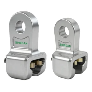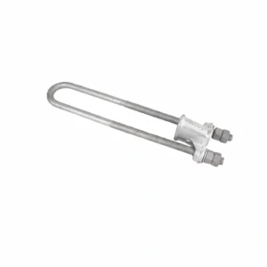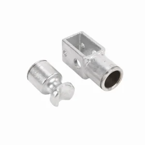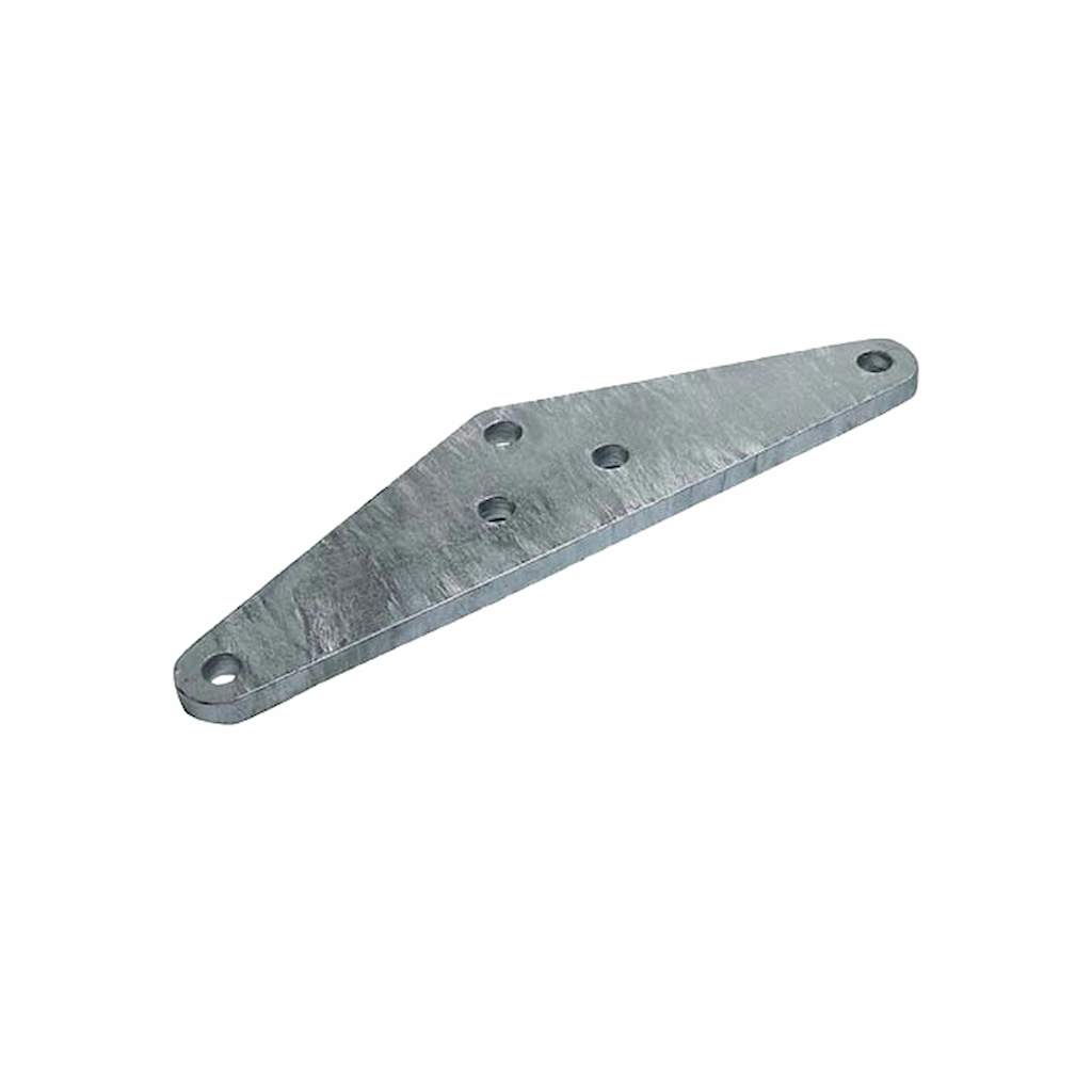
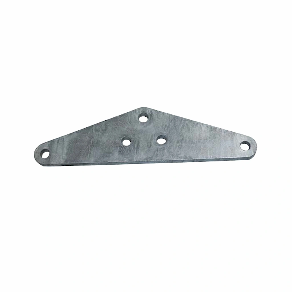
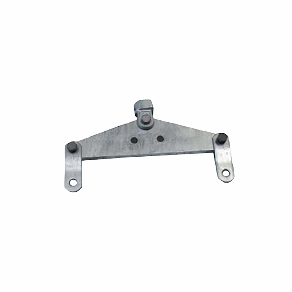
Triangular Yoke Plate Product Overview:
Utility construction teams specify the Triangular Yoke Plate to establish safe, structural linkages across electrical grids. The hardware is designed for straightforward installation and long-term durability in outdoor environments.
- Hangs suspension insulator strings directly and securely onto utility towers.
- Connects overhanging wire clips specifically utilized for straight pole towers.
- Secures tensioning wire clips required for non-straight pole towers.
- Delivers excellent corrosion resistance, ensuring a long operational lifespan.
Key Features of the Triangular Yoke Plate:
Integrating this certified Triangular Yoke Plate hardware into your network guarantees mechanical stability alongside highly flexible B2B procurement terms:
- Manufactured under strict quality control plans within ISO 9001, ISO 14001, and ISO 18001 certified facilities.
- Buyers benefit from zero minimum order quantities (MOQ) on initial purchases (500 pcs for further orders).
- Highly competitive low-cost pricing complemented by fast quotations and dependable after-sale service.
- Free initial samples are available (buyer covers freight) to verify quality before bulk EPC material orders.
Triangular Yoke Plate Applications & Use Cases:
Built for reliable structural linkage, the Triangular Yoke Plate provides steadfast holding power for complex electrical grid setups. Field crews utilize this hardware to execute safe connections across LV and MV networks:
- Forming and hanging suspension insulator strings on overhead power line towers.
- Linking vital hardware securely within large-scale electrical substations.
- Securing straight pole and non-straight pole tower wire clips seamlessly.
- Serving as custom OEM anchor hardware tailored to specific municipal utility requirements.
Triangular Yoke Plate Technical Specifications:
Review the exact engineering constraints of the Triangular Yoke Plate below to verify that the hardware aligns perfectly with your designated tower parameters. The data sheet details the dimensions and rated failure loads for the entire L-series lineup.
Series Dimensional & Load Data:
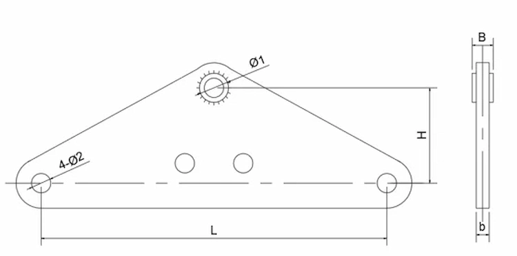
| Cat. No. | Dimensions (mm) | Failure Load (kN) | |||||
|---|---|---|---|---|---|---|---|
| Φ1 | Φ2 | b | B | H | L | ||
| L-1040 | 20 | 18 | 16 | 16 | 70 | 400 | 100 |
| L-1240 | 24 | 18 | 16 | 16 | 70 | 400 | 120 |
| L-1640 | 26 | 20 | 18 | 18 | 100 | 400 | 160 |
| L-2140 | 30 | 20 | 16 | 26 | 100 | 400 | 210 |
| L-2540 | 33 | 24 | 16 | 30 | 110 | 400 | 250 |
| L-3040 | 39 | 26 | 18 | 32 | 110 | 400 | 300 |
| L-4255 | 45 | 30 | 24 | 38 | 250 | 550 | 420 |
| L-5040 | 45 | 33 | 30 | 38 | 110 | 400 | 500 |
| L-6045 | 51 | 39 | 32 | 42 | 200 | 450 | 600 |
| L-6050 | 51 | 39 | 32 | 42 | 250 | 500 | 600 |