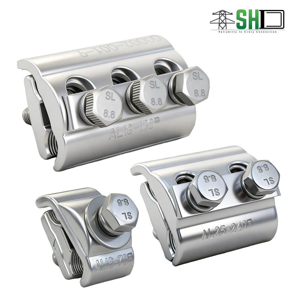
Aluminum parallel groove clamp Overview:
Untreated aluminum-to-aluminum joints are highly susceptible to severe oxidation, which dramatically increases contact resistance and causes dangerous thermal bottlenecks over time.
Deploy our specialized APG Clamp to secure your transmission jumper connections flawlessly:
- Hot-forged to confirm maximum aluminum volume density, ensuring the surface temperature of the joint never rises higher than the reference conductor itself.
- Pre-coated with a high-grade oxide-inhibiting compound, preventing metal degradation and maintaining long-term grid stability.
Key Features & Benefits:
Optimize your engineering specifications instantly with these highly reliable, rigorously tested advantages:
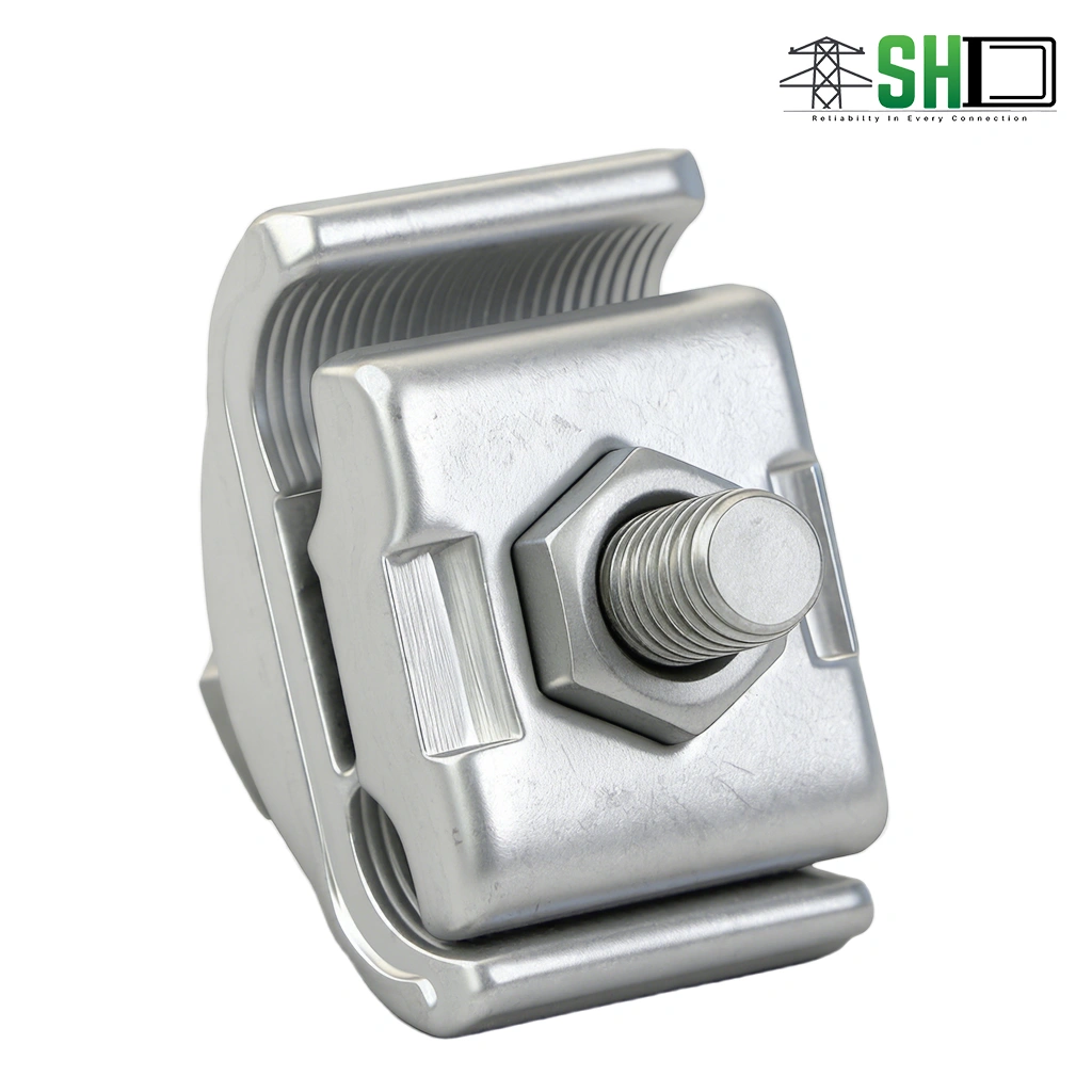
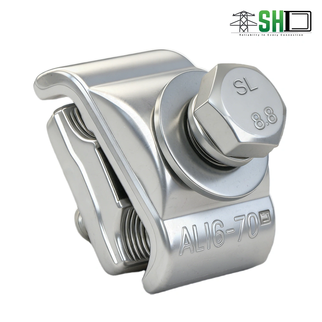
- Constructed from hot-forged aluminum to guarantee structural density.
- Supplied with an oxide-inhibiting compound to prevent metal oxidation.
- Provides a safe slip strength reaching 10% of the reference conductor.
- Ensures the equivalent length is strictly not greater than 1.1 times the conductor.
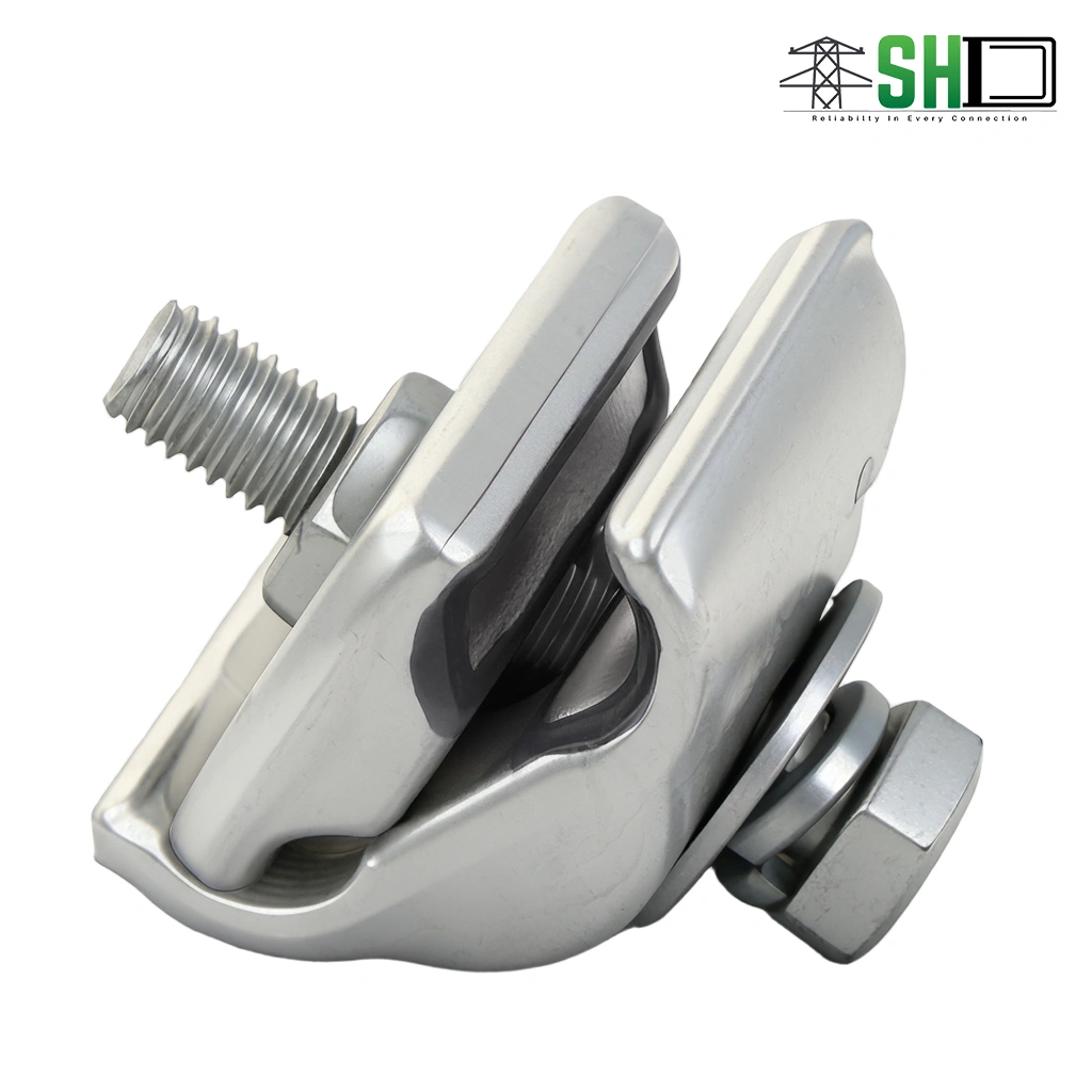
- Engineered for fast, easy, and secure field installation on non-linear poles.
Applications & Use Cases for Aluminum parallel groove clamp:
Integrate this dynamic connecting hardware to establish completely fail-proof overhead distribution systems.
This heavy-duty unit is the definitive engineering choice for the following critical utility tasks:
- Splicing overhead aluminum strand conductors safely using a standardized Aluminum parallel groove clamp.
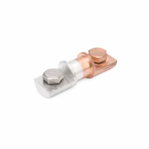
- Securing non-linear pole jumper connections efficiently with a tested AL-AL pg clamp.
- Managing steel-reinforced aluminum power lines securely without compromising tensile strength.
Technical Specifications:
Review the comprehensive mechanical capacities, IEC standard compliances, and dimensional data below to ensure perfect alignment with your engineering tenders.
| Technical Parameters & Standards | |
| Upper & Lower Jaw Material | Hot-forged Aluminium Alloy |
| Fasteners | Hot dip galvanized or stainless steel (Grade 8.8) |
| Mechanical Failure Load | 10% of the reference conductor’s tensile strength |
| Design & Testing Standards | IEC 61284, DIN 48072 |
Conductor Application Data (AL-AL):
| Part No. | Cross Section (mm²) | Diameter (mm) | No. of Bolts | Size of Bolt | ||
|---|---|---|---|---|---|---|
| Min. | Max. | Min. | Max. | |||
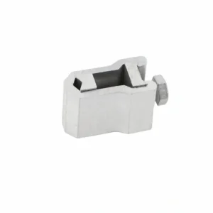
| APG-A1 | 16 | 70 | 5.1 | 10.5 | 1 | M8 x 40 |
| APG-A2 | 25 | 150 | 6.3 | 16.1 | 1 | M8 x 45 |
| APG-B1 | 6 | 35 | 2.7 | 8.1 | 2 | M6 x 35 |
| APG-B2 | 16 | 70 | 5.1 | 10.5 | 2 | M8 x 45 |
| APG-B3 | 25 | 150 | 6.3 | 16.1 | 2 | M8 x 50 |
| APG-B4 | 25 | 240 | 6.3 | 20.3 | 2 | M10 x 60 |
| APG-B5 | 35 | 300 | 7.5 | 22.4 | 2 | M10 x 70 |
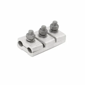
| APG-C1 | 16 | 70 | 5.1 | 10.5 | 3 | M8 x 45 |
| APG-C2 | 25 | 150 | 6.3 | 16.1 | 3 | M8 x 50 |
| APG-C3 | 25 | 240 | 6.3 | 20.3 | 3 | M10 x 60 |
| APG-C4 | 35 | 300 | 7.5 | 22.4 | 3 | M10 x 70 |
Dimensional Data:
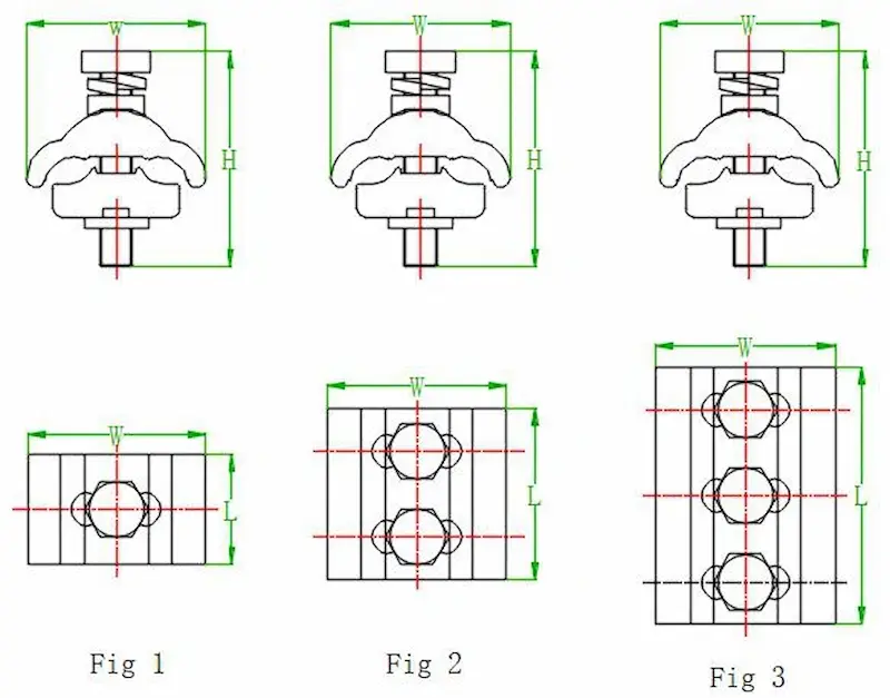
| Part No. | Fig. | L (mm) | W (mm) | H (mm) | No. of Bolts |
|---|---|---|---|---|---|
| APG-A1 | 1 | 25 | 41.5 | 45 | 1 |
| APG-A2 | 1 | 30.5 | 45 | 50 | 1 |
| APG-B2 | 2 | 40 | 41.5 | 50 | 2 |
| APG-B3 | 2 | 49.5 | 45 | 55 | 2 |
| APG-B4 | 2 | 63 | 58 | 66 | 2 |
| APG-C1 | 3 | 60 | 41.5 | 50 | 3 |
| APG-C2 | 3 | 69 | 45 | 55 | 3 |
| APG-C3 | 3 | 90 | 58 | 66 | 3 |
| APG-C4 | 3 | 104 | 64 | 76 | 3 |