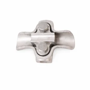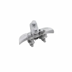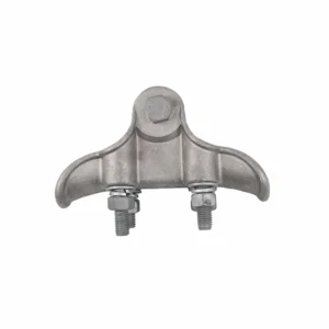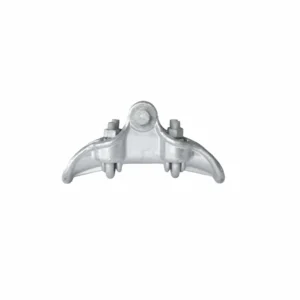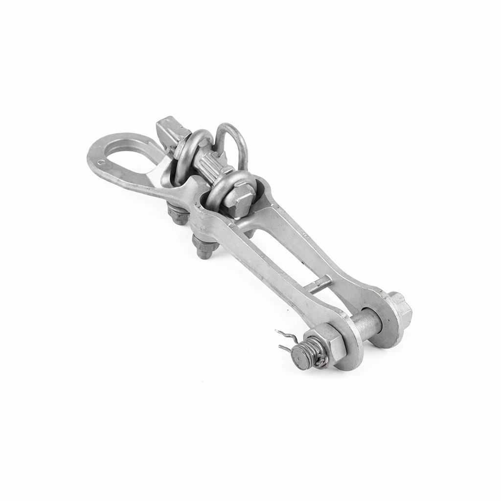
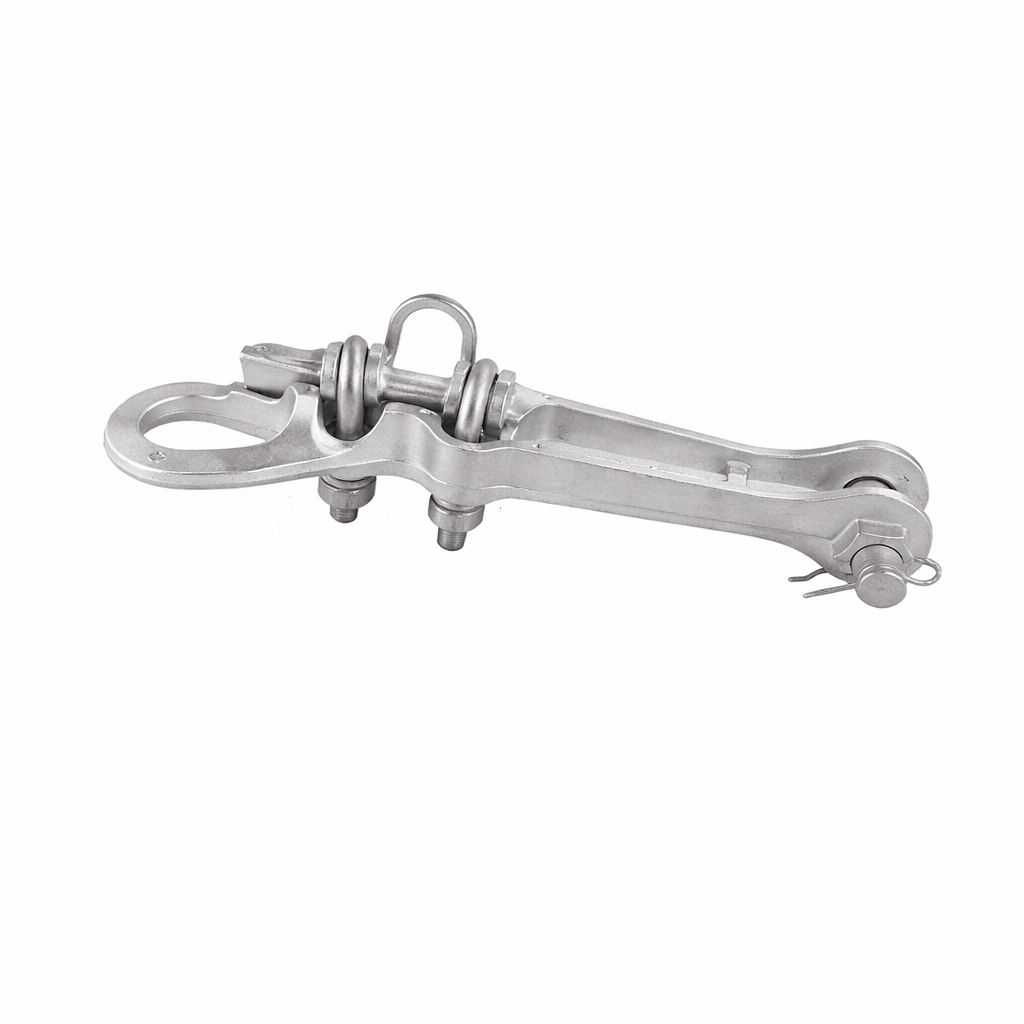
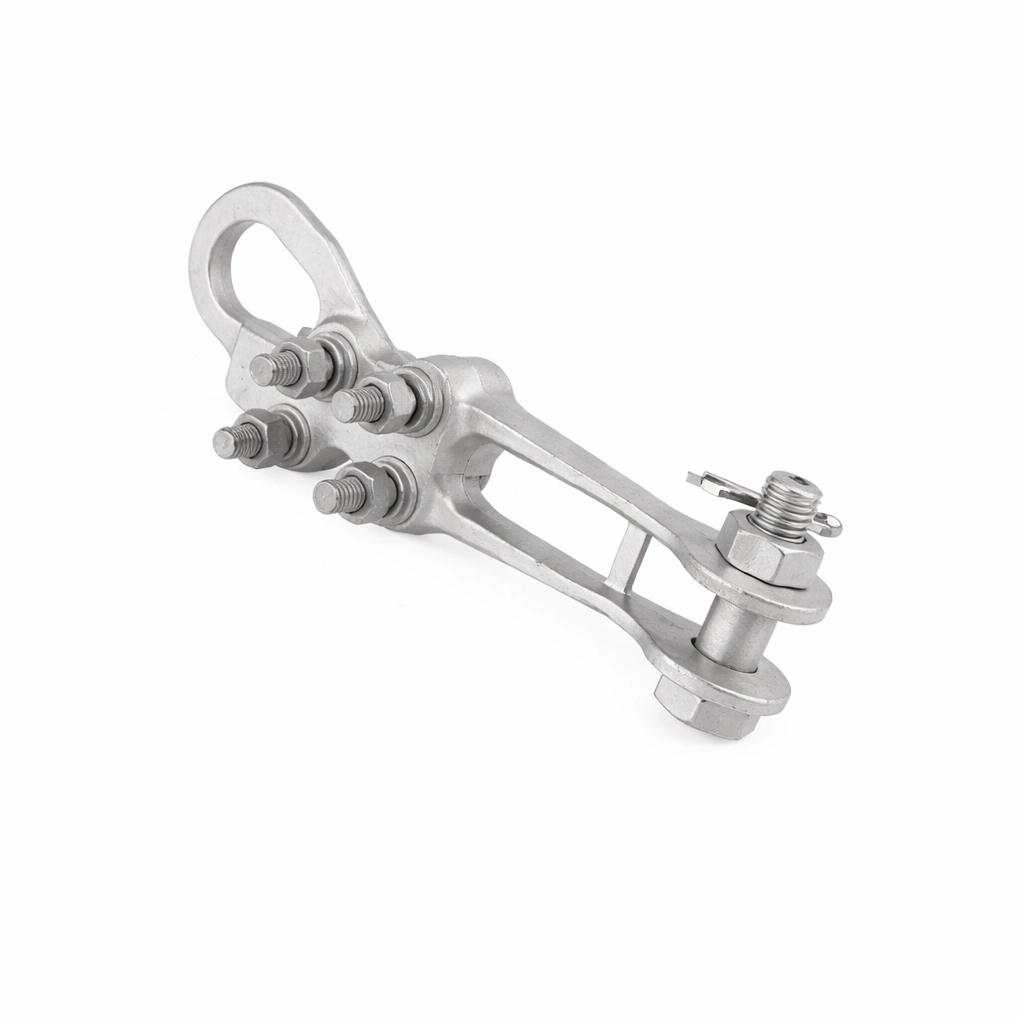
NLZ Dead End Strain Clamp Overview:
Failing to secure aerial networks with proper grip force can compromise substation integrity and lead to severe structural line drops.
Deploy our specialized hardware to guarantee a permanent, fail-proof overhead connection:
- Manufactured with an energy-saving aluminum alloy body and pressing block, ensuring maximum mechanical efficiency and excellent electrical conductivity.
- Equipped with a highly durable stainless steel closing pin and hot-dip galvanized steel components for ultimate environmental resistance.
- Functions flawlessly as a heavy-duty straight line dead end clamp, guaranteeing the operational grip force continuously remains above 90% of the rated tension without damaging the line.
Key Features & Benefits:
Optimize your overhead distribution networks instantly with these rigorously tested, high-performance physical advantages:
- Constructed strictly for reliable quality, offering extremely strong and durable performance under heavy mechanical loads up to 45KN.
- Provides exceptionally good electrical conductivity when safely deployed as compression, hydraulic pressure, or explosion-type hardware.
- Ensures remarkably easy installation processes on strain poles, significantly reducing utility deployment times.
- Operates seamlessly alongside standard straight line strain clamp units for comprehensive overhead infrastructure reinforcement.
Applications & Use Cases For dead end strain clamp:
Ensure the absolute stability of your power distribution infrastructure with hardware built for extreme tension endurance.
This unit is the definitive engineering choice for the following critical utility tasks:
- Fixing bare aluminum conductors and steel core wires safely for overhead transmission lines operating reliably up to 20kV.
- Securing substation fixed wires, lightning rods, and tower lines permanently against severe mechanical stress.
- Upgrading tensioning insulator strings smoothly and securely utilizing our highly robust Deadend Strain Clamp.
Technical Specifications:
Review the exact conductor diameters, U-Bolt configurations, ultimate tensile strengths (U.T.S), and structural dimensions below to perfectly align with your network hardware requirements.
NLZ Series DIMENSION AND TECHNICAL PARAMETERS:
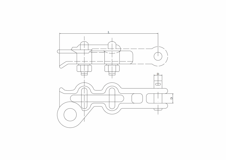
| Type | Conductor Dia. (mm) | Dimensions (mm) | U-Bolt No. | U.T.S (KN) | Weight (kg) | ||
|---|---|---|---|---|---|---|---|
| L | C | D | |||||
| NLZ-1L | 3.8-9.4 | 114 | 18 | 16 | 2 | 20 | 0.6 |
| NLZ-2L | 5.8-10.4 | 180 | 18 | 16 | 2 | 35 | 0.84 |
| NLZ-3L | 7.6-15.2 | 195 | 19 | 16 | 2 | 45 | 1.05 |
| NLZ-4L | 11.7-22.4 | 240 | 24 | 16 | 2 | 45 | 1.34 |