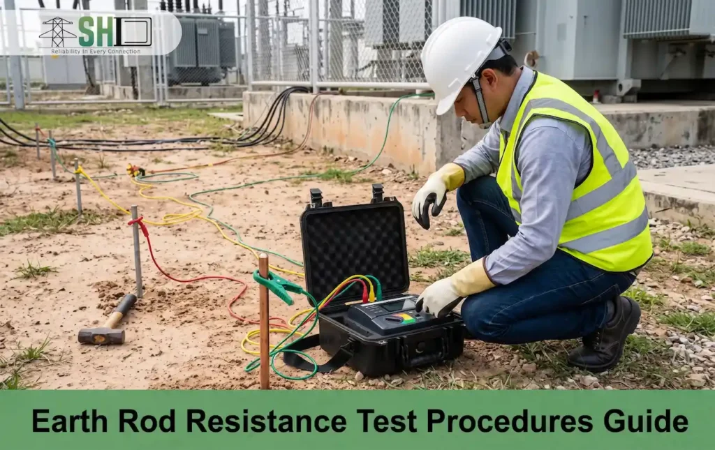
Earth rod resistance test procedures are fundamental to ensuring the safety and reliability of any electrical grounding system. This critical diagnostic evaluation measures the effectiveness of a grounding electrode in dissipating fault currents safely into the soil. Over time, environmental factors like shifting soil moisture, temperature fluctuations, and chemical corrosion can significantly degrade an electrode’s performance, increasing the risk of equipment failure or hazardous electrical shocks. By regularly performing earth electrode resistance test, engineers can accurately verify that the grounding system maintains a low-resistance pathway, ultimately protecting vital infrastructure and personnel from catastrophic electrical faults.
What is the Earth Rod Resistance Test?
An Earth Rod Resistance Test is an electrical measurement used to check how easily fault current flows from a grounding system into the surrounding soil.
Read More: Ground Rod Sizing and NEC Code Requirements
Why Industrial Facilities Need Regular Grounding Checks?
Industrial facilities need regular grounding checks to protect workers from electric shocks, prevent catastrophic equipment damage, and avoid electrical fires, so they need an earth rod resistance test:
- Personnel Safety: Prevents fatal electrical shocks by directing fault currents safely into the earth.
- Equipment Protection: Dissipates voltage surges from lightning or line faults, protecting expensive machinery from burnout.
- Fire Prevention: Eliminates stray currents and static buildup that can ignite fires or explosions in hazardous areas.
- Power Quality: Minimizes electrical noise and transients, ensuring sensitive automation and control systems operate without data errors.
- Compliance Assurance: Meets mandatory safety regulations and legal standards, avoiding severe fines and insurance liabilities.
- Soil Changes: Detects changes in ground resistance caused by shifting soil moisture, temperature, and corrosion over time.
Essential instruments for the earth rod resistance test
The essential instrument for an earth rod resistance test is a dedicated earth resistance tester (such as 3-pole or 4-pole fall-of-potential meters), supplemented by auxiliary stakes, connection cables, and optional current clamps.
- Earth Resistance Tester (or Earth Ground Tester): A specialized digital meter that injects a known test current and measures the resulting voltage drop.
- Auxiliary Current Stake (Probe C): A metal spike driven into the soil at a distance to pass the test current into the earth.
- Auxiliary Potential Stake (Probe B): A second metal spike driven into the soil between the earth rod and the current probe to measure voltage potential.
- Test Leads / Cables (Spool Wires): Long, color-coded connector wires used to link the earth tester to the rod under test and both auxiliary spikes.
- Hammer or Mallet: A heavy tool used to firmly drive the temporary auxiliary metal spikes into the ground.
- Wire Brush or Cleaning Tool: Used to clean corrosion or dirt from the top of the earth rod and ensure a secure connection for the test clamp.
Crucial Electrical Safety Precautions Before Testing
In some earth rod resistance test need isolate and disconnect the earth electrode from the main electrical system before conducting a ground rod resistance test to prevent dangerous feedback or shock hazards.
- Electrical Isolation: Disconnect the earth conductor from the electrode under test to isolate it from live systems and prevent stray fault currents from entering your testing equipment.
- Permit to Work (PTW): Obtain the necessary safety work permits or authorization from the control room or site supervisor before starting any grounding tests.
- Personal Protective Equipment (PPE): Wear rated insulating gloves, safety boots, a safety helmet, and high-visibility clothing during the procedure.
- Stray Current Check: Verify that the test area is completely clear of unexpected AC or DC leakage currents that could disrupt measurements or create active hazards.
- Equipment Inspection: Check all test leads, auxiliary spikes, and your earth resistance tester for frayed insulation, cracks, or broken clamps before use.
Read More: What Does a Ground Rod Do for Grid Safety
Steps to execute different earth ground measurement methods
Accurate earth ground measurement ensures electrical safety and system stability. Different earth rod resistance test methods accommodate various environmental constraints, building types, and system configurations to verify low-resistance paths to the ground. The earth electrode resistance test procedure:
1- Fall-of-Potential Method (Three-Pole Test)
- Disconnect the grounding electrode from the building’s electrical system.
- Configuration and distances determine how to drive two auxiliary stakes (current and voltage) into the earth from the electrode.
- Connect the tester terminals to the target electrode and the two auxiliary stakes.
- Pass a known current between the electrode and the outer current stake.
- Measure the voltage drop between the electrode and the inner voltage stake.
- Calculate resistance using Ohm’s Law for the earth resistance test value, typically automated by the tester.
2- Selective Method
- Leave the grounding electrode connected to the building’s electrical system.
- Place the auxiliary stakes exactly like the Fall-of-Potential method.
- Clamp an induced current clamp around the specific grounding leg being tested.
- Measure the total current flowing through the entire grounding network.
- Isolate the current of the single electrode via the clamp to calculate its specific resistance.
3- Stakeless Method (Clamp-On)
- Identify a complete grounding loop system, as this method requires a continuous circuit.
- Clamp the specialized dual-induction tester around the grounding conductor.
- Induce a known voltage into the grounding circuit via the first clamp loop.
- Measure the resulting current flow through the circuit via the second clamp loop.
- Read the loop resistance directly from the screen without using any physical earth stakes.
4- Soil Resistivity Method (Wenner Four-Pin Test)
- Drive four auxiliary stakes into the ground in a straight line with equal spacing (a).
- Connect the two outer stakes to the current terminals of the tester.
- Connect the two inner stakes to the voltage terminals of the tester.
- Run a constant current through the outer stakes to generate a voltage drop across the inner stakes.
- Record the resistance value (R) displayed on the meter.
- Compute soil resistivity (ρ) using the formula: =2aR
Effective solutions to reduce high ground electrode resistance
To reduce high ground electrode resistance, the most effective solutions include using multiple parallel electrodes, increasing the electrode length, and treating the surrounding soil with conductive materials.
- Deepen the electrode: Drive the ground rod further into the earth to reach soil layers.
- Use multiple electrodes: Install additional ground rods in parallel, spacing them apart at a distance greater than their length, and bond them together.
- Chemically treat the soil: Apply ground enhancement materials (GEM), bentonite clay, or conductive concrete around the electrode to artificially increase soil conductivity.
- Increase electrode diameter: Use thicker ground rods to increase the surface area contact with the soil (offers minor resistance reduction).
- Install a grounding grid: Use a mesh network of interconnected copper conductors for large facilities to lower resistance and control step/touch potentials.
- Replace the electrode material: Switch to high-conductivity materials like copper-bonded steel or solid copper, or use hollow copper pipes filled with electrolytic salts (chemical ground rods).
Upgrade Your System with Reliable Sihedan Grounding Parts
Sihedan provides premium Overhead Power Line Hardware alongside advanced Grounding and Bonding products such as earth rod to cable clamp, earth rod driving stud, and Bare Earth Wire. Enhance grid safety, protect critical infrastructure, and ensure uninterrupted electrical performance with our high-quality, engineered components.
- Superior Material Longevity: Manufactured using high-grade, corrosion-resistant copper and galvanized steel to withstand severe outdoor environmental conditions.
- Maximum Electrical Conductivity: Engineered to ensure optimal low-resistance pathways, preventing equipment damage and ensuring rapid fault current dissipation.
- Compliance and Certification: Fully compliant with rigorous international utility standards, guaranteeing certified safety and operational reliability for power grids.
- Streamlined Installation Design: Designed for rapid, secure deployment by utility crews, reducing field labor time and minimizing maintenance overhead.
Ensure absolute grid safety with our certified grounding components. For direct factory pricing, bulk OEM orders, and custom specifications, visit our Contact Us page, reach out via WhatsApp, or email info@sihedan.com.
FAQs
What is the acceptable earth resistance value under NEC rules?
The NEC generally requires a grounding electrode resistance of 25 ohms or less; if it exceeds this, a second supplementary electrode must be installed.
How far apart must auxiliary test stakes be placed in soil?
Auxiliary test stakes must be placed 10 to 20 feet apart from each other, following the 62% rule to ensure accurate, non-overlapping resistance measurements.
Can you measure grounding resistance using a basic multimeter?
No, you cannot measure grounding resistance with a basic multimeter because it lacks the necessary alternating current, high voltage, and multi-probe testing capability.
How does winter soil freezing alter earth electrode readings?
Winter soil freezing significantly increases earth electrode resistance readings because frozen water acts as an insulator, drastically reducing soil conductivity around the rod.
Leave a Reply